
A fractured-reservoir well test
Before this page
The coupled poroelastic problem, whose equations are solved below, Building a fractured-rock material for the material, and Thick-walled cylinder, the mechanical example this one extends.
A synthetic fractured reservoir produced by a vertical well, in which the fracture apertures follow the effective stress and the permeability follows the apertures. The model, the microstructure and the two comparison cases are those of Barthélémy and Daniel (2011), § 3.2.
Everything here is three-dimensional and anisotropic: two vertical fracture families make the reservoir conduct six times better along
This page is static
Figures come from scripts/fe/arma2011_welltest.jl, run by hand and committed. A documentation build never runs a coupled reservoir simulation.
The microstructure
Solid phase
| family | dip | dip azimuth | radius | aperture | conductivity | density |
|---|---|---|---|---|---|---|
| 1 | 90° | 22.5° | 1 m | 10⁻³ m | 6.7·10⁻¹¹ m³ | 0.37 |
| 2 | 90° | 157.5° | 1 m | 10⁻³ m | 6.7·10⁻¹¹ m³ | 0.37 |
props = Dict(:C => C_SOLID, :K => TensISO{3}(1.0e-18))
rve = RVE()
add_phase!(rve, :M, Ellipsoid(1.0), props; fraction = :rest)
for φ in (π/8, 7π/8)                       # dip 90° ⇒ the normal is horizontal
    add_phase!(rve, gensym(), ConductiveCrack(1.0; conductivity = 6.7e-11,
               euler_angles = (π/2, φ)), props; density = 0.37)
end
mat = FracturedPoroelasticRock(rve, SelfConsistent(); ω₀ = (5.0e-4, 5.0e-4),
                               k_matrix = 1.0e-18)
One microstructure, every coefficient the coupled problem needs:
ℂʰᵒᵐ₃₃₃₃ = 3.189·10⁴ MPa
𝐁       = diag(0.9157, 0.7212, 0.4911)             anisotropic Biot tensor
1/M     = 2.837·10⁻⁵ MPa⁻¹
𝐊       = diag(9.66·10⁻¹², 5.63·10⁻¹¹, 5.81·10⁻¹¹) m²
Both families are vertical, so
Geometry, mesh, and why a quarter is enough
A cylinder of radius 3500 m and height 200 m, produced along its axis. A fracture normal is defined up to a sign, so reflecting about
The radial layers are geometric (cylinder_sector_grid): the pressure drop is logarithmic in
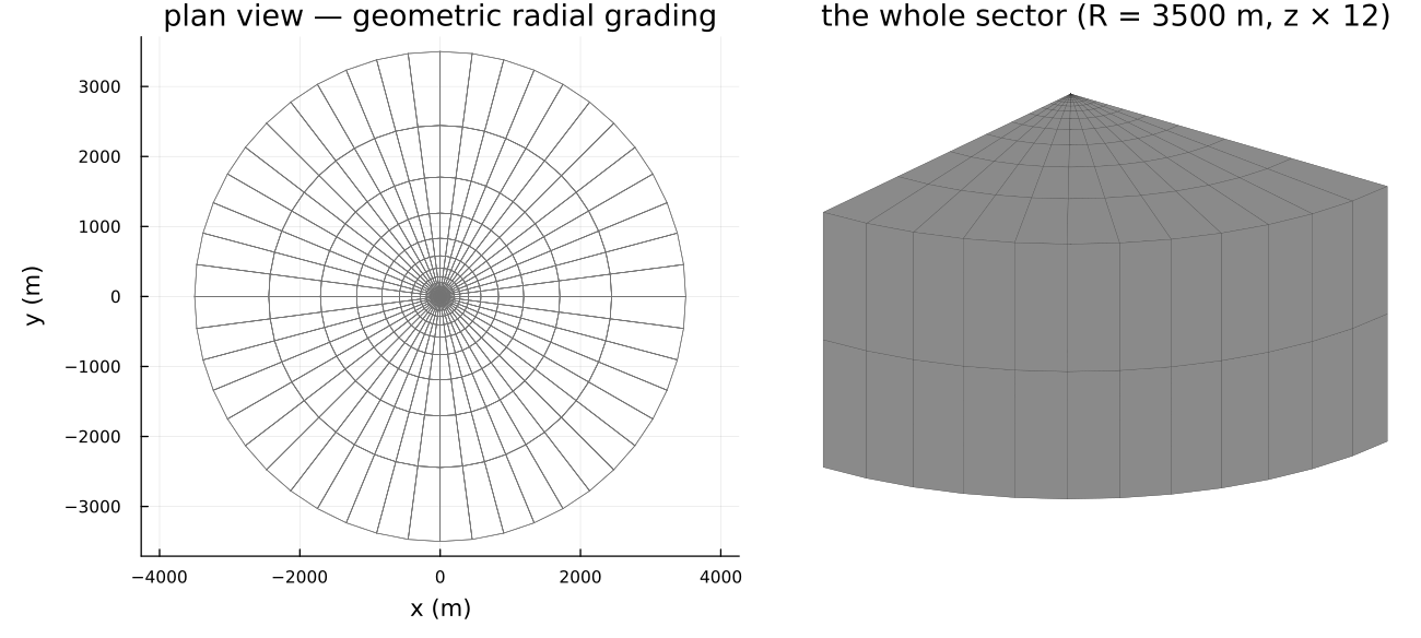
| 672 hexahedra, 4524 dofs | |
| 28 geometric layers | |
| draw-down 24 h at | then shut in for 48 h |
Prescribed flow rate on the well wall, no flow through the top and bottom faces,
The solve
The weak form, its backward-Euler discretization and the four tangent blocks are on the coupled poroelastic problem; the driver is thirty lines around mfh_poro_element! and knows nothing about fractures.
EXT.mfh_poro_element!(
    Ke, re, cvu, cvp, material, xe[URANGE], xe[PRANGE],
    states[cellid(cell)], states_old[cellid(cell)], Δt, mob[cellid(cell)];
    u_range = URANGE, p_range = PRANGE, cache = cache
)
Two models are compared, as in the reference:
| M1 | the homogenized properties are computed once and frozen |
| M2 | apertures follow the Terzaghi effective stress, conductivities follow the cubic law, |
Both share the same mechanics: for flat cracks
The pressure field
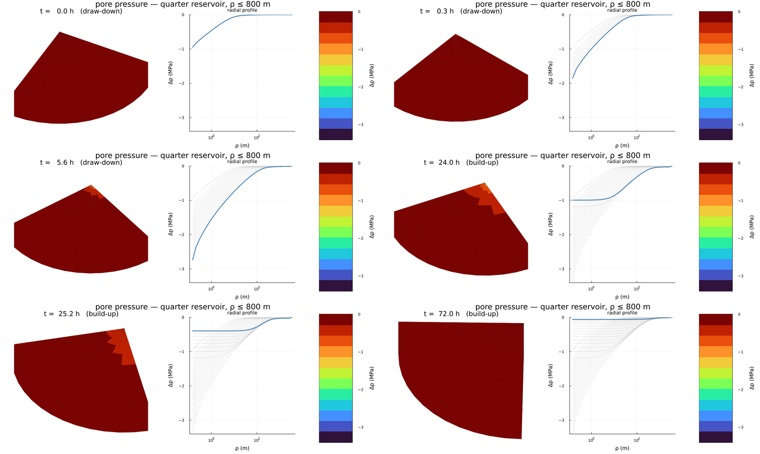
The isobars are elongated along
Well pressure
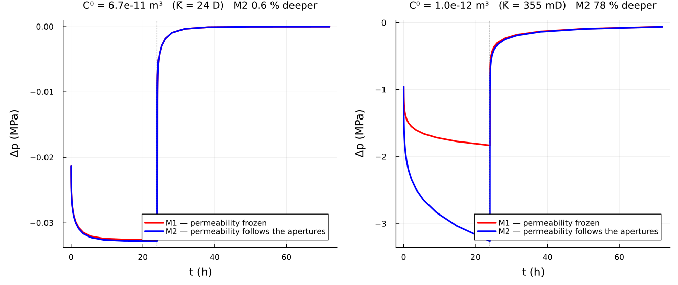
Pressure falls during the draw-down and recovers after the well is shut in; M2 draws down deeper than M1, because the pressure drop closes the fractures a little, the cubic law turns that into a conductivity drop, and a less permeable reservoir needs a larger draw-down to deliver the same rate. The build-up is far less sensitive.
Two cases, and why
Taking the table above literally, the permeability estimate used here gives a 23-darcy reservoir, a draw-down of 33 kPa and a 0.6 % gap between the two models — the left panel, which looks flat because it is flat. The published figures are an order of magnitude away: −1.8 MPa for M1 and a 33 % gap.
Steady radial flow gives
The right panel tests that reading directly: the fracture conductivity is calibrated to
| M1 draw-down at 24 h | M2 vs M1 | ||
|---|---|---|---|
| here, calibrated | −1.83 MPa | +78 % | −70 % |
| published | −1.8 MPa | +33 % | ≈ −50 % |
M1 lands on the published value, and the draw-down is still declining at 24 h rather than stabilized, as published — the diffusion time scales as
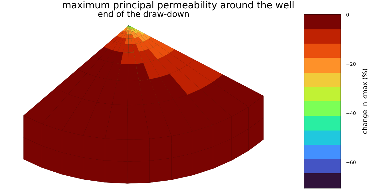
The permeability is reduced near the well, where the pressure variation is most negative, and the reduction is itself anisotropic — the isovalue bands are not circular.
What this reproduces, and what it does not
Reproduced: the microstructure, the joint poroelastic and hydraulic upscaling from one RVE, the Terzaghi-driven aperture update, the cubic law, the coupled u–p simulation and both models — with the published draw-down magnitude once the permeability level is matched, and every qualitative conclusion of § 3.2.
Not reproduced: the reference's self-consistent permeability, which carries a matrix concentration factor built on the order-2 Hill tensor of the effective medium. The estimate here reads each family's saturated contribution in the effective medium without that factor (
fracture_permeability), so the two agree in structure — same percolation mechanism, same saturation — but differ by ≈ 55 on the level and ≈ 2 on the sensitivity. It is not transcribed here because the equations that define it are, in the copy at hand, not legible with enough confidence to implement without guessing.Not shipped: the consolidation column of § 3.1, models M1/M2/M3 — the case where a family actually closes during the loading. Everything it needs is here; see the roadmap.
Where to go next
The finite-element coupling ends with this example. The developer chapter that follows opens with Architecture, the organization of the package for those who extend it, and closes with the Roadmap, which lists the consolidation column of the reference among the pieces left to implement.